Use this relay card with your obsolete PC as dedicated controllers for a variety of uses: turning on/off lights or other devices around the home, office, laboratory or factory come to mind. all that is needed is the interface to connect it to the real world.
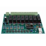
The hardware PCB plugs in directly to the parallel (printer) port of you computer. It carries 8 relays. Each relay is switched on or off by one bit of the output byte which usually goes to your printer to print a character. Two types of software are provided: one operates under DOS while the other is a more detailed program which runs under Windows 3.1.
HARDWARE
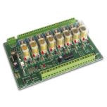
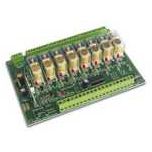
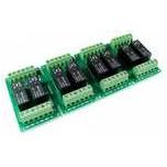
The PCB contains eight identical switched relay positions, power input positions to the relays (either 2.5mm jack center positive, or via the terminal block) and a DB25 connector to the parallel port of a PC> To keep the kit simple no input latches have been put on it. If your application is important then you should use a UPS to keep the computer operating in the case of a mains power supply failure. If the board is accidentally disconnected from the parallel port then the 10K pull-down resistors will turn the relay off. The diodes protect the transistors from the back-emf which is occurs when the relay is turned off and its magnetic field collapses.
The relays are under direct control of the output byte (8 bits) from the parallel port. When a pin is high a nominal 5V is presented to the base resistor R1. Since there is a fixed 0.6V drop across the BE junction of Q1 there is 4.4V across R1 (5V - 0.6V0. So by Ohms law 1.33 mA flows through the 3K3 resistor. There is also 0.6V across the 10K pull-down resistor which draws 0.06mA. If we assume a hFE of 100 for Q1 then 127mA flows through the CE leads of Q1 when it is turned on. Since the 12V relay turns on at around 30mA this current is more than enough to turn on the relay. The relay has a coil resistance of around 400 ohms and a coil power consumption of 30mW.
Note that this analysis assumes 5V is available from the parallel port pin. In more modern computers this may not be so. If the LED turns on but the relay does not then you will know that the transistor is not saturating. Reduce the value of R1 (and all the similar resistors) to 2K7 from 3K3 will probably fix this. Measure the voltage on the collector. When the relay is on then the voltage should be around 0.1V. If it is 3V - 4V then the transistor is not fully on.
The relays are rated at 10Amps for 125 volts but the PCB and connectors would never handle this. The relays were selected to be at least twice what the current flow would be in order to have a long life span and good reliability. In order to have the PCB carry up to 5 amps of current you would want to add capacity to the PCB traces. The kit not modified would be able to carry 2- 3 amps. You could scrap of the solder mask and tin the copper trace or use copper wire from point to point. If it keeps its cool, it will last longer and be more reliable. In order to drive even larger loads use a relay specific to your load. Electrical supply houses sell large relays with double poles for switching large AC loads safely. Use the contacts on the QK74 to supply the coil voltage to the larger relay. Safety first, make sure you do not make any short cuts where large loads are concerned.
You can write your own programs in any language to output a byte to the printer port and the bits which are high will turn on the corresponding relay. The overlay on the PCB shows which bit in the output byte turns that particular relay on. For example, output 00010001, or 11 in hex turns on relays 1 and 5. Each relay number is also marked on the overlay for easy reference.


Validate your login
Sign In
Create New Account