

1.3 Inch 240x240 RGB TFT IPS LCD Module 7pin
SKU
RGBOLEDTFT1.3
In stock
$8.95
Overview
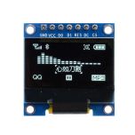
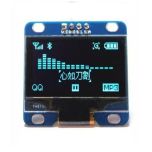
1.3" 240 x 240 RGB TFT IPS LCD Module
7pin ST7789 Chip
1.3" 240 x 240 RGB TFT IPS LCD Module
7pin ST7789 Chip
1.3″ OLED LCD is full color and high resolution 240 x 240 pixels with wide viewing angle.
Features
Operates at 3.3V, so if using with a 5V MCU, include logic level shifters on the data lines to prevent damage. The module don't have a 3.3V regulator so you must power with 3.3V.
This is a write only device and doesn't need the SPI MISO line hooked up. The module also doesn't bring the CS pin out to the interface which helps to lower the pin count. Unfortunately, it can't be used with other SPI devices on the same bus simultaneously.
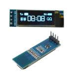
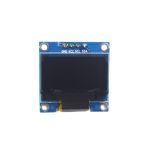
Connecting the display via a 7 pin header.
1 x 7 Header
EVALUATION
Breadboard friendly with a 7-pin header on the back. It can be inserted into a breadboard or a 7-pin female connector to mount the display. PCB mounted display which helps provide support. Don't press on the glass portion of the display when inserting into a breadboard. Use the pin headers.
Connect VCC to 3.3V and GND to ground on the MCU.
Connect the SPI lines. SCL goes to the SPI SCL line on the MCU and SDA goes to the SPI MOSI line on the MCU. This pins will be different depending on the MCU. On the Arduino UNO, the SPI SCL is pin 13. On the Arduino MEGA 2560, it is pin 52. MOSI is pin 11 on the Uno and pin 51 on the Mega 2560.
Connect DC to pin 8 and RST to pin 9. The BLK pin can be left unconnected and will leave the backlight on.
When using a 3.3V MCU, the lines can be connected directly. If using a 5V MCU, then you need to use a logic level converter.
Install the Arduino-ST7789-Library. Manually download from GitHub since it's not available in the Arduino IDE library manager. This is a modified version of the original Adafruit library. Easy to use with the displays that do not have a CS pin as well as those that do. https://github.com/ananevilya/Arduino-ST7789-Library


Please complete your information below to login.
Sign In
Create New Account