

Dual QK108 Upgrade
SKU
QK108U
In stock
$29.95
Overview
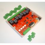
Dual Realy Card Upgrade Kit
Dual Realy Card Upgrade Kit
The master kit contains relays 1 to 8 and inputs 1 to 3. The slave kit contains relays 9 to 16 and inputs 4 to 6. When the master receives a relay or input number that belongs to the slave kit it simply sends the command on to the slave kit for processing.
CONSTRUCTION DETAILS
br>There are FOUR things to do with the upgrade kit and two assembled QK108s:
1. replace the existing firmware in QK108 with the two supplied, identical QK108 dual firmware chips.
2. remove the front and rear panels of each QK108. You will have to unsolder and remove the LED bezels and reset switch. Add the Master panel and Relays 1-8 to one QK108, and the Slave panels with Relays 9-16 to the other.
3. Remove IC7, 4N25 from both QK108s. Insert two wire links either soldered on the bottom of the PCB underneath the IC7 socket or jumpered as shown:
" Pin 1 to 5
" Pin 2 to 4 4.
The two QK108 kits need to be connected together via a data link. The data link uses Input 4 of each original kit. Use the short length 2-wire cable supplied to connect
input 4 of each kit together, with the + terminals connected to each other and the - terminals connected to each other. Connect using the 2-pole screw terminal plugs supplied with each QK108 kit.
Longer wire lengths are possible between the two kits. However the data link uses TTL level pulses which will be affected by long wire lengths. Anything over 1 metre (36 inches) may cause problems. Try it and see!
Only one of the kits connects to the PC via the serial port. This will be the Master unit. It doesnt matter which kit you connect to the PC. However, for ease of use, the front and rear panels are numbered differently for the master and slave so it makes sense to connect the kit labeled Master to the PC serial port.
COMMANDS
The commands are the same as those in the original QK108 kit. There are no new commands. The only thing that has changed is the syntax of each relay command because we are dealing with 16 relays instead of 8. Relay numbers now require two digits instead of one, including a leading zero if required.
A set of simple text commands is used to control the relays, return their status or read the inputs. Each command consists of a string of ASCII characters followed by carriage return (Enter !).
The # character is output as a prompt to indicate the kit is waiting for a command. Each character received is echoed back. On completion of each command, good or bad, a carriage return/line feed combination is output followed by the # prompt. If the command or parameter is invalid, the command is ignored and a ? is output before the next # prompt. Note: " Commands are not processed until the carriage return character is received. " Commands can be in upper or lower case. " Relays are numbered 01 to 16. Relay number 00 (zero) indicates ALL relays. " Inputs are numbered 1 to 6. Input number 0 (zero) indicates ALL inputs. Where a hex byte or word is used, each bit represents its corresponding relay or input. Bit 0 indicates relay or input 1, bit 1 indicates relay or input 2, etc. If the data link between kits is broken (or the slave kit not working) an following error message will be returned. Timeout error: Check connection to other kit This will only happen with commands that return the status of a relay or input in the slave unit ie. S00, S09-16 or I0, I4-6.
Nxx Turn a relay ON (where xx = relay number)
Eg. N03 - turn on relay 3
N10 turn on relay 10
N00 - turn on ALL relays
Fxx Turn a relay OFF (where xx = relay number)
Eg. F03 turn off relay 3
F10 turn off relay 10
F00 turn off ALL relays
Txx TOGGLE a relay on/off (where xx = relay number)
Changes the state of a relay (ON to OFF, OFF to ON)
Eg. T03 toggle relay 3
T10 toggle relay 10
T00 toggle ALL relays
Rhhhh Set ALL relays directly
hhhh is a 16-bit hex word. Each bit within the word indicates whether the corresponding relay is operated or not. If the bit is 1 then the relay is operated, if the bit is 0 then the relay is released. Bit 0 represents relay 1, bit 1 is relay 2, &. bit 15 is relay 16.
Eg. R5555 relays 1,3,5,7,9,11,13,15 ON, all others OFF
R0F0F relays 1-4, 9-12 ON, all others OFF
Sxx relay STATUS (where xx = relay number)
A 0 (zero) is returned if the relay is released, 1 if operated. The command S00 returns the status of ALL relays. A 16-bit hex word is returned. Each bit within the word indicates the status of the corresponding relay.
Eg. S03 returns the status of relay 3
S10 returns status of relay 10
S00 returns the status of ALL relays
Ix INPUT status (where x = input number) A 1 is returned if the input is active or enabled, 0 otherwise. The command I0 returns the status of ALL inputs. An 8-bit hex byte is returned. Bits 0-2 indicate the status of inputs 1-3. Bits 4-6 return the status of inputs 4-6. Bits 3 and 7 are unused and are set to 0.
Eg. I1 returns the status of input 1
I4 returns the status of input 4
I0 returns the status of ALL inputs
A special command, ?, will print the software revision date.
IF IT DOES NOT WORK Refer to the original K108 documentation. If the master link seems to be working but not the slave then check the data link between them. Does the + terminal connect to + and - to - ?
PART LIST DUAL K108
AT89C2051 uC......for IC1.......2
pre-programmed, identical firmware chips
Front & rear panels, Master....1 set
Front & rear panels Slave......1 set

Please complete your information below to login.
Sign In
Create New Account