

Timer Kit Using Capacitor Discharge
SKU
QK85-3
In stock
$10.25
Overview
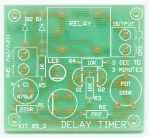
Classic Timer Kit
|

The relay is activated
immediately when the switch is pressed.
Then after a period of
time (about 2 to 400 seconds with the component values
supplied with the kit) the relay times out.
This has application anywhere that a brief pulse is required to turn
on a device for anywhere from 2 seconds to about 6 minutes.
For example, a night light, delay to leave a room before an alarm is turned on, photographic timer.
However, in this circuit we do not use an IC to do the timing.
We use the discharge of an electrolytic capacitor.
Normally the relay is off. This is because Q1 is turned off
by the potentiometer resistance and R2. Q1 controls Q2.
And Q2 controls the relay. All three are normally off.
When the switch is pressed two things happen.
First the base of Q1 is connected to the +12V supply via R3. Q1
turns on.
Resistor R3 limits the amount of current which can flow into the base. Q1 turns on Q3 which in turn
activates the relay.
The LED turns on to show that the
relay is activated.
The normally connected output of +12V drops to zero.
The second thing to happen when the switch is pressed is
that current also flows into capacitor C1 and charges it.
So when the switch is released the charge in the capacitor
keeps Q1 turned on until the charge has decayed away through R2 and the potentiometer.
(There is also a small
leakage through the transistor due to the base current
of Q1.)
You can easily increase the time for the charge to
decay by increasing the resistance of the potentiometer.
If you want longer times you can experiment with a 1mF capacitor or higher.
MAINS SWITCHING
These on-board relays on these kits
should not be used to switch the mains power directly
even though they are rated to do it.

Please complete your information below to login.
Sign In
Create New Account