This mini-VOX - voice operated relay - is based on a circuit published in Silicon Chip, 9/1994, p31. We have improved it by putting an on-board Koa potentiometer in order to adjust the sensitivity. The idea behing a VOX is that instead of the user pressing a switch to activate a relay, the sound of the users voice itself activates the relay. This gives hands-free control over devices like tape recorders.
ASSEMBLY
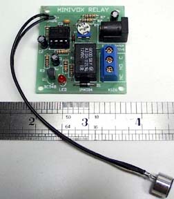
Check of the Components against the Listing. Follow the overlay. Note that the microphone should be located on two wires (not supplied) some distance away (like 1ft to 2 ft) from the PCB. It should not be mounted on the PCB otherwise vibration from the relay could trigger it continuously. Note one component is located under the IC so the IC socket has to be used.
OPERATION
Audio is picked up by the microphone and fed to the opamp IC1a. This is connected as a non-inverting amplifier with a gain of 151 or +43.6dB. The 100pF capacitor across the 150K feedback resistor rolls off the high frequency response above 10kHz to eliminate RF. The output at pin 1 feeds two diodes, D2 and D3 which function as a half-wave voltage doubler. These rectify the audio signal to produce a DC voltage across the 2.2uF ecap, C2 which is directly proportional to the input audio sound level. This DC voltage is fed to pin 5 the second opamp IC1b. This is connected as a comparitor. A resistive voltage divider applied about 2V to pin 6. Once the DC voltage across the 2.2u ecap rises above the voltage at pin 6, pin 7 pulls high. This turns on transistor Q1 which activates the relay and turns on the LED. Q1 remains on while the DC voltge at pin 5 is above that at pin 6. Because of the high opamp gain of IC1a, and with the voltage doubler gain the circuit has a fast response time. However, the release time takes about 3 seconds determined by the time constant of C2, R5 (the 1M resistor) and the pin 6 threshold voltage. D1 is connected across the relay to protect Q1 when the relay turns off (back-emf.) Connect the microphone on leads up to 2 feet away from the PCB. Connect the negative of the microphone (the pin connected to the microphone case) to the -ve on the PCB microphone position. Battery 12V power may be used. D4 acts as protection for the circuit in case power is connected the wrong way. Current drain when off is 5-7mA. It is about 35mA when activated. Sensitivity may be varied with the 200K Koa potentiometer. A good working VOX level is about R6+R9 of 150K. But if you want more sensitivity then you can reduce R9 to 22K or less and turn the trimpot R6 to maximum sensitivity (fully clockwise.) The off delay time may be adjusted by varying R3 and R4. Reducing R3 will result in a longer release time. You could change the release time constant (C2 & R5) to say 30 seconds and use the VOX as a light switch with this delay time before turning off. Increase C2 to say 10u and R3 to 3M3.


Please complete your information below to login.
Sign In
Create New Account