This "Wiper" Timer Module, although designed for vehicle use, it can also be used in applications requiring repeated power cycles. Such as irrigation, dross and residue sweepers and lighting displays.
- Time Interval : Adjustable from 3 to 30 seconds
- Power supply : 12 VDC / max 40 mA
- Installs between the wind shield wiper switch and wiper motor. Can be used in any car.
- Gives your car the "intermittent" wipe mode, instead of either having the wipers on or off.
- Installs across the low speed circuit of the wiper motor.
- Use the normally open contacts to supply the slow speed circuit.
- The timer will turn on for a few seconds then turn off.
- When the potentiometer is completely rotated to the left (counterclockwise) the off time will be minimal
- When the potentiometer is completely rotated to the right (clockwise) the off time is at it's maximum (about 45 sec).
- The potentiometer has an incorporated ON/OFF switch. Rotate to the left, it will click, turning the unit off. Ensuring the timer does not start another wipe cycle.
- The park contact should supply the wiper motor until the wiper makes a complete cycle.
- If not then this unit will probably not work for you.
- It is easy to determine, just shut the wipers off while they are in the middle of the cycle.
- If it returns to park position then you are all set.
ON OFF switch is incorprated into the speed adjust pot, fully CCW turns it off.
LED indicator for the state of the relay.
- PCB dimensions: 58 x 50 x 22mm OR 2 1/4" x 2" x 1" (L x W x H)
- The PCB has four mounting holes one in each corner of the PCB.
- Check for an enclosure here: Enclosures
- The pot has an ON/OFF switch incorporated and it would be possible to add a short length of wire (100 cm or aprox 36 inchs 5 wires in total) to remotely mount the control.
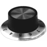
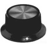
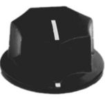
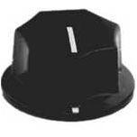
Chose a knob for the potentiometer here in our Hardware section <-- We include a small plastic knob with the MXA041
Keep in mind that there are far to many wiring configurations for us to be able help with all installs.
Knowledge of automotive wiring is required for successful installation.
Basically this is just like a switch that goes across the low speed switch.
The easiest way to make the unit work is, locate which wire is the slow speed wipe.
Connect a lead / jumper to GND (changed from positive after the feedback below) the other end will be used to probe the wiper motor wires.
Which ever one starts the slow wipe cycle is the one you are after. These leads should be present at the wiper switch.
Now connect the COM pin of the relay to GND ( changed from Positive ), the NO pin goes to the wire you have just discovered.
The wipe cycle should complete a full revolution when you remove the trigger wire.
These instructions have been updated (May 2019). Any feedback will help others.
If you cannot find the low speed wipe using GND try a positive trigger voltage.
All of this assumes the motor has a common ground, anyone know of a system that uses Positive as a common? Please let us know..
Here is a note from Scott and his installation.
I got to test the wiper motor to ground Friday morning. It helped to realize that Chevy had grounded the switch, rather than the wiper motor. I wired it up with a small plug in harness into the little box I bought with the wiper kits. I also wired a momentary switch into the circuit for a one cycle function.
I really felt kinda silly when I realized how GM wired the wipers. 20 years ago, when I last rewired a car (at that time, from scratch), this wouldn’t have gotten past me.
In case this comes up again, these GM truck wiper motors are not wired exactly like the motor wiring diagram below, though functionally the same. Instead of one 12v in, there is a 12v input to each circuit, one for the high, and one for the low. The terminal that functions as the low/high circuits that is wired to the switch, and then to ground is next to each 12v input terminal.
Since this reverse method of wiring nulls the listed instructions, it leads to a confusing situation. It might help to add something about the switch possibly wired to ground and to, in that case, or really any case, find where 12v is available in the wiper circuit before using the 12 v jumper. In a situation like GM’s wiring, finding the low speed wipe by probing with 12v will not work. It also could possibly damage something. I blew a fuse when I first probed it with 12v as I touched one of the terminals that would go to the switch, thinking power, by the test description, should obviously be running through the switch with ground at the wiper motor.
I will note that the wiring harness I had did not help. I had just rewired the truck with a Painless Performance wiring harness specifically made for the 1967-72 GM pickups. The aftermarket harness is an excellent harness, much improved over the stock harness, and uses the stock color codes, well, all except the wiring harness section to the wipers. For some reason, instead of the light blue and yellow wires in the original harness, all those wires are light blue, making it difficult to trace where power (yellow) input is, especially while standing on your head under the dash. The wipers worked with both the OEM and the Painless aftermarket harness, but having 3 light blue wires wire tied together up in a basically dark hole didn’t make tracing wiring for the delay easy. I plan on discussing with the company the problem of changing the color code for these wires. It makes no sense not to use yellow. It reminds me of the crazy things I’ve seen in Italian car wiring harnesses.
After trying to find the slow speed circuit unsuccessfully, I cut the wiper harness section of the Painless harness out and spliced in the original harness with the yellow wire in. Then I got your info leading me (or us) to realize this circuit was wired differently than would work in your original test.
I like the little circuit. I was a bit bemused when I saw the 8 pin DIP in the circuit. I instantly recognized the 555 timer IC. I used many of those to make various timing circuits back in the 1970’s. I hadn’t thought about them in years.
I wonder if you have sold any of these for the old Chevy pickups because there is a system made specifically for those trucks and is sold by the companies that sell restoration parts. Those boxes are an inferior device which requires the wiper switch be turned on and switched on and off to cycle through speeds. I suspect it is as annoying to use as it sounds. However, they seem to sell.
I may buy more of these as I know other people who own these trucks, and I already have one who wants me to wire one up for their truck.
Check out our Resistance Activated Relay Module designed for older shifter mechanisms with impedance output. VK034


Validate your login
Sign In
Create New Account