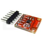
I2C Multiplexer TCA9548A Breakout Board

SKU
TCA9548A
In stock
$3.95
  • Buy 2 for $3.49 each and save 12%
  • Buy 5 for $2.95 each and save 25%
-
+
Overview
I2C Multiplexer TCA9548A Turn one I2C port into 8

This TCA9548A I2C multiplexer module can bind up to eight I2C of the same address. It serves selects and sends commands to the selected set of I2C pins. Using it is quite easy, the multiplexer is on I2C address 0x70 (but can be adjusted from 0x70 to 0x77), write a single byte with the desired multiplexed output number to that port so that future I2C packets will get sent to that port.

You can connect 8 of these multiplexers on each of 0x70-0x77 addresses, controlling 64 I2C addresses

Pin supply:

  • Vin  - this is the power pin. Since the image uses 3 V to 5V DC to power the board, it requires a voltage supply identical to the microcontroller (Arduino ex - 5V)
  • GND  - ground

I2C control pins:

  • SCL  - This is the clock pin of the image, connect I2C clock pin microprocessor
  • SDA  - This is the image data pin, connect I2C data pin microprocessor
  • RST  - It is pin reset, reset the image multiplexer. It is connected to HIGH, the reset connected to ground.
  • A0  A1 A2  - Pins Selection Multiplexer. The default mode is to address 0x70 and pins are connected to LOW (GND). ConectaÅ£ii to come to set addresses from 0x71 - 0x77.
  • A0  is the least-significant bit (if connected to the HIGH address increment 1)
  • A1  is the second least-significant bit (if connected to increment the address HIGH 2)
  • A2  is the third least-significant bit (if connected to increment the address HIGH 4)

I2C multiplexed pins:

  • SDX  and  SCx : There are 8 sets of pins  SDX  and  SCx from SD0 / SC0 to SD7 / SC7. They are multiplexed pins, each is a completely separate I2C bus. So it can have 8 devices with identical address as long as each is a separate I2C bus. (These pins have internal pullup sites!)

QUICK LINKS: